|
|
|
|
|
||||
|
|
Rotor Research Helicopter Info Site | |||
|
|
|

|
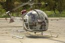
BELLL 47G – 3B1. TC’s Tips to make your Daily/Pre-flight Inspection safer.
The following hints can be incorporated with the daily and pre flight inspections required by BELL and the aircraft log book maintenance statement.
Ø Start at the left (pilot’s) side of the helicopter and work your way around the machine in an anti-clockwise direction. Duplicate the left side inspection on the right hand side where required. Ø Standing outside the helicopter, lean in and check that the cyclic and collective control frictions are off. Read the next 5 tips carefully before moving the cyclic, collective and pedals through their full range. Ø Take care anytime that you are tightening the collective friction. Over tightening can easily strip the thread in the friction control rod attach nut under the cabin. If the nut is stripped, it is possible for the collective to suddenly rise if you take your hand off it while the rotors are turning. This could be a disaster if it happened on the ground at flight RPM. Ø Hold the throttle fully closed, while checking the collective lever for full up and down freedom of travel. This action stops the carburetor accelerator fuel pump from over priming and flooding the engine Ø Yes - its OK to move the cyclic in a circle to check its full range of movement on the cyclic control rigging stops. It's better to then move the cyclic fore and aft and then laterally, feeling for any resistance between the full fore/aft and lateral rigging stops. This because it is important to realise that each cyclic control servo cylinder acts in two directions and therefore a positive check of the “feel” in BOTH directions of each power cylinder is required. Ø Lean back and observe all control systems on the engine side of the firewall while moving the cyclic through its full range with your left hand to see they are not hitting or binding on anything. Particularly eyeball each rod end to see that it is tight. Worn rod ends cause delay with control inputs to the rotor disc and make hovering harder. Ø lean inside and push the left and right Tail Rotor pitch control pedals fully back and forward. Listen for the banging noise from under the cabin floor as the pedals hit their max rigging stops. Have your mechanic check the tail rotor rigging at the tail rotor gearbox if no noise is heard. You may not be getting full tail rotor pitch travel. This could turn into a really serious in flight control problem if the tail rotor cannot obtain either full high or full low pitch angles. Ø If a door is fitted, check that both retainer pins are through their hinges when the door is closed and latched. If a part of the system is damaged or out of alignment causing a pin to not protrude through the hinge, the door may come off in flight and hit your main or tail rotor. Ø Starting with the left front, check the skid uprights for weld cracks. Ø Check the rear skid cross tube attach saddle clamps for security and grip (is the cork or rubber gasket loose?) Ø Look through both the front and rear cross tubes. You should be able to see daylight at the other end. If you cannot see through a tube, it may have too much permanent set due age or a hard landing. Usually your mechanic can roll the tube 180 degrees as a fix. Ø Check the condition of both fan belts – about 3/8 inch bow in when pushed hard in with one finger. Tighten loose belts – they may fling off if loose and under high power circumstances and the engine may seize within one minute due to lack of forced cooling air. Make sure any excess grease from the engine/transmission adaptor plate or fan bearings does not fall onto the belts. Ø Use a torch and check the edges of both fan belts for fraying and also inside the belt cogs for cracks which may go into the belt ply Ø NOTE: If any oil is leaking from the transmission side of the Top Fan Drive Pulley or if the pulley can be made to move or rock in/out or in a horizontal or vertical plane, DO NOT FLY THE AIRCRAFT UNTIL THE CAUSE HAS BEEN DETERMINED. I REPEAT – Do not fly the aircraft! It may be that the fan drive gear or its support bearings are stuffed. CHECK THE ENGINE OIL PRESSURE FILTER FOR MAGNETIC METAL CONTAMINATION. Ø At the bottom of each hydraulic servo is a pin with a round head passing through the clevis on the servo rod. On the other side of the clevis, it has a castellated nut with a safety split pin through it. You must be able to freely turn the pin. If hydraulic fluid is leaking from the lower seal on the servo onto the pin, clean it off as it can attract dust and grit which in turn can cause wear on the pin. Ø Place both hands in the middle of the left side of the fuel tank. Push on/off against the fuel tank, checking for security. Sometimes the tank works loose on the main frame/basket attach bolt or one of the small rear attach brackets may be broken. Ø Before any flight, condensation or small water droplets clinging to the inside of the tank may be dislodged if the tank is “slapped” with palm of your hands.
Ø Flight
Tip: Plan fuel consumption at 70 litres per hour. Dip the
tank after 2 hours. On level ground, fuel 1 inch (approx) deep in
front of forward tank baffle gives you 8 –10 minutes
Ø Make sure that both fuel filler caps are latched in a “down” position. If latched up, water can seep thru centre pin if the “O” ring is worn. By keeping the latch “down”, water will not accumulate around centre pin and will drain overboard. Ø Look for cracks in the horizontal airframe tube near where the fuel tank attaches (between the basket/airframe attach bolt and the rear of the tank). These can be caused by internal corrosion. If the frame cracks completely through, there is potential for the tail rotor drive front short shaft to become disconnected in flight. Ø Look for loose or missing engine cylinder rocker cover screws. These tend to vibrate loose when cork gaskets are used under the rocker cover. It is preferable to use the new red neoprene gaskets for long life, no oil leaks and retention of the rocker cover screws. Ø On turbo machines – check that no exhaust manifold pipe to cylinder holding studs have shaken loose and gone overboard. Often you can hear this in flight or at ground idle as a loud ticking noise as the hot exhaust gas exits the hole. When a stud comes loose or comes out, the white hot exhaust gas can erode the alloy cylinder flange, distort the exhaust pipe flange, damage/burn a spark plug and make for sluggish turbo response. Ø Observe that no green or blue Avgas fuel stains are coming from the intake manifold pipe/cylinder attach area gaskets. A blown gasket in this area can lead to sluggish performance. Erratic fuel air mixtures can cause a cylinder to run lean and damage the piston or exhaust valves. Check for any suspected leaks by gently spraying a garden hose in the area while the engine is idling. If a gasket is faulty, water will be sucked in and cause the spark plugs to short out on the cylinder with the faulty intake gasket Ø If this is the first time that you will have flown the machine or some one else has recently been flying it in a dusty environment– remove the filter cover and remove and inspect the air filter. Look inside the housing for signs of dust bypassing the air filter or passing through any cracks in the flexible tube connecting between the housing and turbo. Ø Check that a non thinking mechanic has not drilled a hole inside the filter housing to get his screwdriver in to adjust the density controller! If there is a hole and it isn’t sealed – hot engine air and damaging dust will be able to flow through/bypassing the filter. Ø While the air filter is out – shine your torch in on the turbo impeller and inspect for damage on the blades such as nicks, scratches or where the blades might have been rubbing on the turbo casing. Grip the centre of the impeller and try to move it up/down, or in/out, it should only have a minimal amount of movement; excessive play may indicate a stuffed turbo. Ø Note: There are two types of turbocharger – heavy and lightweight. The heavyweight – identified by having four studs or bolts securing the large diameter exhaust pipe to the turbo itself - should have no free play; the lightweight has a small amount. Ø When refitting the air filter, smear some rubber grease on both the ends to ensure a good seal between the filter and the filter seals. Ø Turbo flight tips:
1 The screw that adjusts the fuel pressure regulator is loc wired correctly to stop it coming loose in flight. 2 The bottom of the mounting flange on the pump has a threaded hole to allow the fitment of a tube to drain any fuel/oil leakage that main accumulate in the enclosure between the pump and the engine. Check that no person has fitted a solid blank to block this hole - True – I have seen this! 3 Before every flight, check that fuel is not dripping from this area. Do Not Fly if there is any sign of a constant drips, as it may be an indication that the pump is about to fail. This could lead to complete engine failure in certain circumstances.
Before proceeding further down the left side of the machine to the tail rotor, clamber up on the left rear side of the transmission to inspect “Up Top”. Do not grab a hand hold on the front tail rotor drive short shaft to help yourself up as you may damage it.
Now complete the remainder of your inspection down the tail boom to the tail rotor:
1. To snag any slivers indicating breaks or frays in the weave of the cable 2. To wipe them clean to look for shiny wear flats where they pass thru pulleys. (Grease on cables attracts dust – dust works into the cables – the cables wear) 3. The rag also stops pain and blood caused by your fingers being ripped open by any cable frays.
COCKPIT: Start up Checks and Tips: (see B47 Pilot Notes Page)
Check: Nothing to jam the T/R pedals in the chin bubble.
Check: Turn the master switch on and check that all temp gauges reading ambient at the first start of day – if not how do you really know if you are under or over temping?.
Check: Oil Temp switch: Oil temp priority = transmission.
Check: If the Door(s) off – secure the seats etc with the seat belts so they are not sucked out the opening in flight and hit the T/Rotor.
Check: Nothing to jam the dual collective, if fitted. Make sure that the dual collective is not restricting full down collective otherwise auto rotation could be embarrassing besides extremely dangerous.
Remember: Hot start – Nil or no more than one throttle prime. Cold start – 3 - 4 throttle primes. Below Zero Ambient cold start: Lift the collective full up – prime with the throttle 4 times holding the throttle in the full open position for about 3 seconds on each stroke – then collective down, throttle closed and start with full carb heat on. Flooded engine procedure (smoking exhaust pipe or fuel running from carb filter drain): mixture – lean, mags off, full throttle, clear engine, close throttle, mags on – try start again. Note: Every time you lift the collective or work the throttle you are making the carb accelerator pump push raw fuel into the system. Great if the engine needs it cold. When its hot - all you are doing is keeping the Arabs rich and stuffing your battery as you try to get a flooded engine started.
|
|
||||||||||||||||||||||||||||||||||||||||||||||||||||||||||||
|
|
||||
|
Copyright © 1995 - 2023 The Owner of This Site - (Rotor Research
(ABN) - All Rights
Reserved. Please read our Legal / Disclaimer |
|
|||