Originally Compiled by Pieter Van Dijk, Air Safety
Investigator (Engineer),
Bureau of Air Safety Investigation, January 1997 for
use by TC on his R22 Safety programs
Amended and updated by TC March 2004

Metal Has
Memory!
An Introduction to Metal Fatigue
Introduction
Metal
Fatigue is the most common cause of structural failure in machinery.
What makes metal fatigue such an important issue for helicopters is
that, if it is not properly understood by pilots and maintenance
engineers, it can bite you hard - very hard.

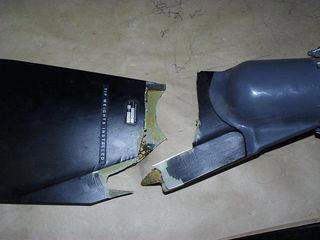
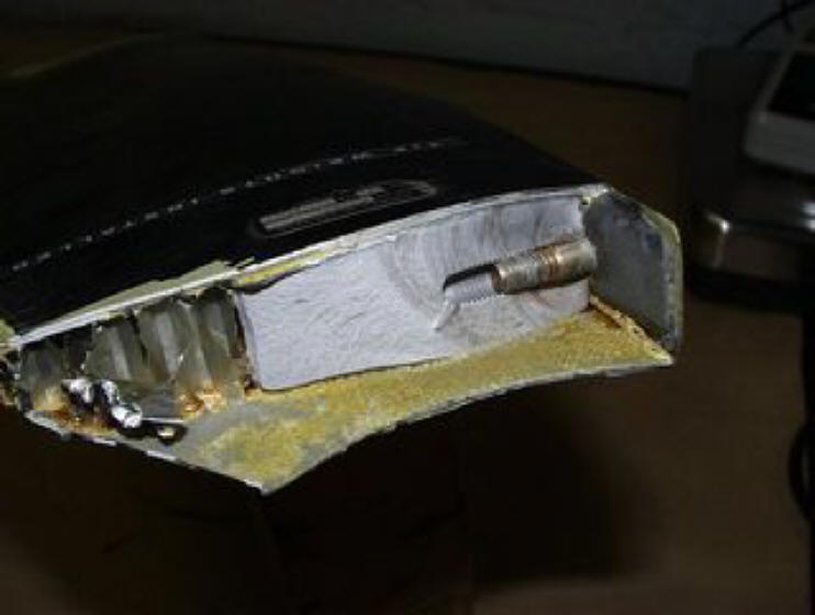
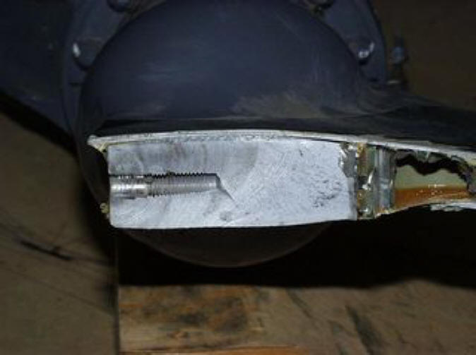
R22 Main Rotor Blade – time exceedence -
fatal
Our
understanding of metal fatigue is only a recent phenomenon i.e. post
World War II as a result of the quest for greater strength from
lighter structures.
Before this time, some metal bridges, liberty
ships and aircraft seemed to crack, collapse or fall apart for what
seemed at the time inexplicable reasons.
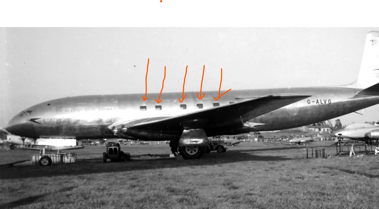
A good example was the British Comet
jet airliner.
Pressurized cabins where new
developments and the change of pressure due climbing and
descending caused the square windows to cause cracks in the
fuselage and the aircraft disintegrated in flight.
Round or oblong windows are now fitted
to modern jet airliners to stop this issue.

Fortunately, our understanding of this type of metal failure mode has
evolved from this early baffling state into a sound engineering tool,
based on metallurgical, mathematical and statistical principles.
What is
especially significant is that metal fatigue can now be controlled
and predicted.
The airworthiness of a helicopter can almost be
guaranteed throughout its entire lifetime, providing everyone follows
certain golden rules.
What is Metal Fatigue?
Metal fatigue is the initiation and propagation of
microscopic cracks, due to the slippage of atomic planes within a
metal component.
This occurs as a result of the repeated application
of stresses and can be caused by:
 |
flight loads |
 |
landing loads |
 |
vibrations |
 |
or simply by just having the engine running. |
Metal fatigue is a dynamic phenomenon. A helicopter in storage will
not develop fatigue cracks!
Generally speaking, in order to occur it
requires moving parts, of which a helicopter has plenty in comparison
to a fixed wing aircraft.
These moving parts represent a mechanism for
the application, and subsequently removal, of a force or a load from
one component to another i.e. On..Off...On..Off... On..Off..
On..Off..etc.
Each one of these “On..Off’s” represents one fatigue
cycle. It is these fatigue cycles that are responsible for the
slippage occurring in the atomic planes that we call metal fatigue.
What is particularly noteworthy is the relatively
small magnitude of applied load required for a fatigue
crack to occur.
This load, and hence the accompanying stress
applied to the component, need only be around 30% of the ultimate load
or stress the component is physically able to withstand.
This
load, however, is generally required to be applied many thousands
of times (fatigue cycles) in order for fatigue cracking to take
place.
The fatigue crack, once developed, will continue to
grow, seemingly with a life of its own, up until a certain point.
This crack growth rate can be anywhere between 0.0000001 - 0.001 mm
per fatigue cycle.
Eventually, the crack becomes so large that the
component is no longer physically able to carry the load for which it
was designed.
The remaining cross-section of the component i.e. the
area as yet unaffected by the fatigue crack, subsequently fractures,
due to overload, and the component fails.
Such a failure can have
significant safety of flight implications.
Enter the term coined by TC – “Metal has Memory”.
All the different metal components that make-up a
helicopter “remember”:
·
every
single load and stress (fatigue cycle) that
they have ever been subjected to
·
for
every single hour, minute and second of operation
·
for
every one of its previous operators – including you.
The net effect of all these fatigue cycles is
cumulative and non-reversible throughout the life of the
component.
It is for this reason that the helicopter’s total
number of hours in service, as opposed to time since new, is so
important.
Recording In-service (Maintenance Release) hours is one of
the most effective ways of measuring the fatigue life of metal
components.
What
Causes
Metal Fatigue?
Many different factors contribute to the particular
fatigue crack propagation rate in any given component.
Each different
size of every different type of metal or alloy has its own unique and
individual susceptibility to fatigue.
The most significant factors affecting fatigue include
 |
the type of operations
(straight and level flying versus mustering operations) |
 |
the magnitude and frequency of loads
(all day everyday operations versus the occasional flight)
|
 |
as well as the quality of the materials concerned
(the presence of flaws or damage to the metal materials leads to
reduced fatigue tolerance). |
Mustering operations are likely to subject the
helicopter airframe to higher stress levels that that of normal flying
operations.
For instance, even one particularly steep (high G)
maneuver could have the equivalent fatigue effect on the helicopter’s
structure or rotors as a week’s - or even a month’s - worth of normal
landings and takeoffs.
A given component’s fatigue life, and hence
time to failure, is in this way reduced by a proportionate amount
of time to what it otherwise might have been if the sever maneuver
had not occurred.
Similarly, conducting flying operations on a regular
basis will subject the airframe to more stress and hence cumulative
fatigue cycles, than would be the case if the helicopter was only
flown on an infrequent basis.
It is for these reasons that the use of bogus or
life-expired airframe components should never be contemplated.
Although from external inspection, the component may appear to be in
reasonable condition, only detailed metallurgical analysis can
accurately determine the true state of its structural integrity.
The
installation of a component of this nature also brings with it more
than you may have bargained for: its memory.
Such a component could be
the weak link in the safety chain.
By installing this component, you
also get its entire collective history of accumulated fatigue cycles
and any damage, despite the fact that it may “look all right” from the
outside.
An easier way to assist with understanding the nature
of metal fatigue is to think of it as a modest inheritance in your
bank account.
 |
Normal flying operations result in
fatigue damage corresponding to withdrawals of only a couple of
dollars per hour. |
 |
High G maneuvers, on the other
hand, cost you hundreds each time they occur. |
 |
Overstress; sets you back
thousands and thousands. |
Unfortunately, there is no mechanism for making
deposits and topping up your account.
There is only so much money
in the bank. When it’s gone ….. it’s gone.

How the Manufacturer Fits In
Nobody knows better than the manufacturer where its
product’s potential fatigue “hot spots” might be.
The manufacturer is
obliged to go to a great deal of trouble, from an early stage, to
conduct simulated fatigue crack tests on the helicopter’s flight
critical components.
This is not only done in order to verify that the
design data used is correct, but also to try and establish whether or
not any potential problem areas exist.
This process commences long
before the in-service fleet approaches the equivalent number of
fatigue cycles and is undertaken by installing the components on test
rigs.
Most of us are familiar with the term “Certification”.
In essence this means that a manufacture has proven the safety of his
product – including fatigue data - to a Regulatory body such as the
FAA or CASA.
Should a particular component on test develop a fatigue
crack, it then becomes the subject of close scrutiny.
Such details as
the number of fatigue cycles required before the crack first appears,
as well as the number of fatigue cycles to when the cracks size
threatens the structural integrity of the component are accurately
recorded.
Accordingly, an appropriate Service Bulletin, servicing
schedule amendment or maintenance instruction is promptly developed
and issued to industry.
These instructions will typically specify that at a
certain number of in-service hours, which is equivalent to the number
of fatigue cycles the test piece was subjected to on the test rig
(including a safety factor), certain inspection, maintenance or
replacement action should take place.
The importance of conforming to
this critical fatigue management information is absolutely paramount
from a safety point of view.
Similarly, this kind engineering feedback
can also be gained by the manufacturer from accidents and incidents in
the field as well as from the advice of operators with high time,
in-service helicopters.
Conclusion
This paper was intended as a brief introduction into
the nature of metal fatigue.
From an operational point of view, it is
not necessary to have an in-depth knowledge and understanding of the
subject - that’s for the rocket scientists.
However, it is extremely
important that every one involved in the operation of all helicopters
complies fully with everything these rockets scientists have to say.
To do otherwise is to act at your own peril, as well as those who may
operate the helicopter after you - inheriting every one of your
fatigue cycles.

The Golden Rules of Fatigue Management
 |
Maintain
accurate records of total airframe, engine and component hours to
allow for the safe management of fatigue in helicopters.
|
 |
Adhere
closely to the manufacturer’s operational and engineering advice i.e.
service bulletins, servicing schedules, newsletters etc to ensure the continued safe operation of the helicopter.
|
 |
Don’t
use bogus, time-expired or accident damaged components even though
they may “look all right”. |
 |
Always
operate the helicopter within the manufacturer’s approved performance
envelope. Excursions from these parameters will compromise the
airworthiness of fatigue critical components. |
 |
Report
all/any exceedence. |
|


